We now have steering. I’ll give a full account of today’s efforts in my daily blog but for now here are some before and after pictures along with some descriptive commentary.
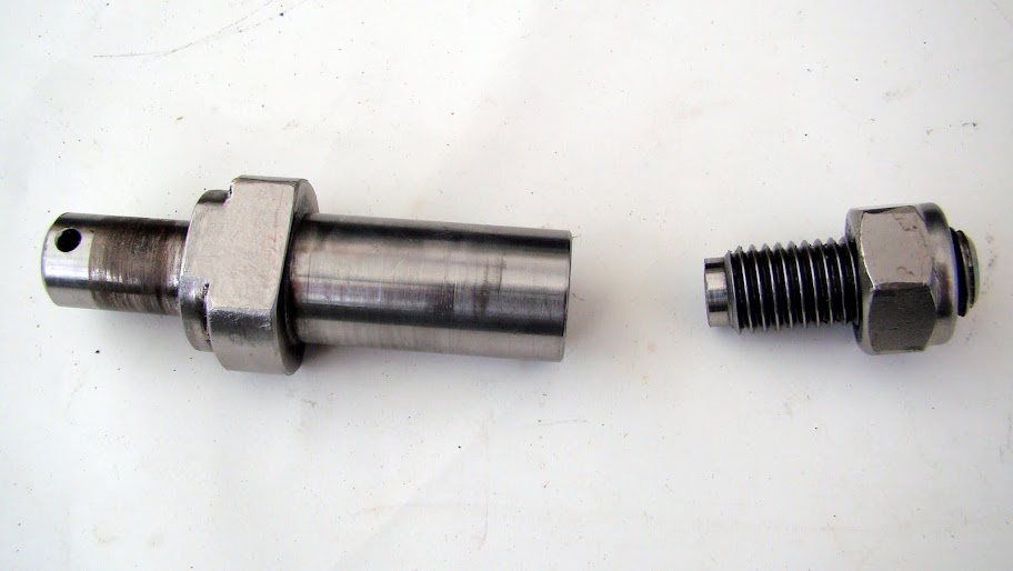
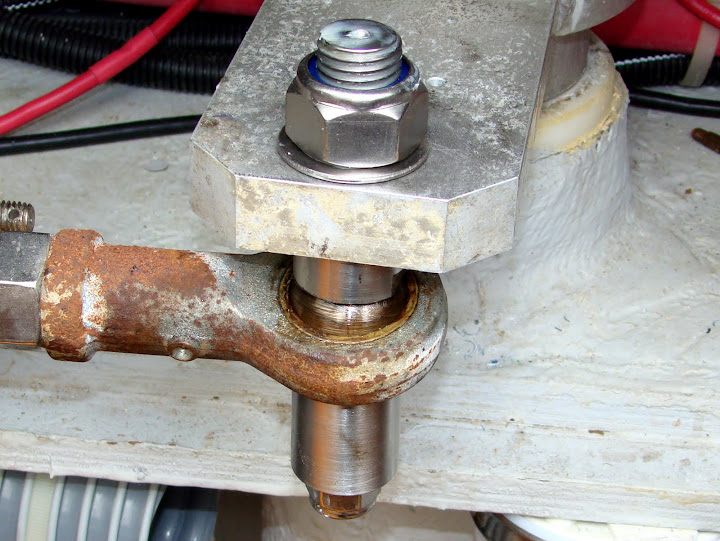
| Here is a picture of the original starboard pin, the one that didn’t break. Although the starboard pin had no requirement to be attached to an autopilot, it was identical reducing the number of distinct parts requiring fabrication. Had this been the port pin, the autopilot would be attached to the left end of the pin and held on with a washer and a cotter pin. The steering assembly fitted to the right of the fatter part (name??). A sleeve separated the steering assembly from the screw which screwed into the flange. Note how where the screw thread terminates, the pin is machined down to the inner diameter of the screw thread. |
Unbroken original pin |
Broken original pin |
So it’s no surprise that the pin failed at the point where it was the narrowest and where it attached to the flange. |
| Looking at the sheared off area you can just see an almost triangular area. This is the area that held on the longest. |
Larger segment of broken pin |
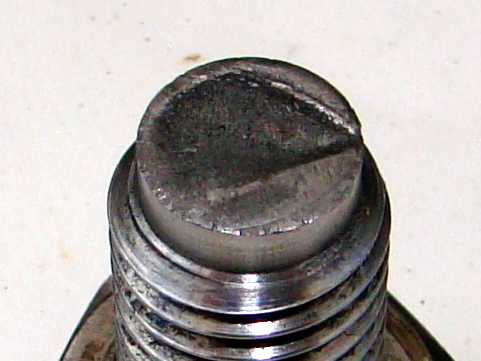
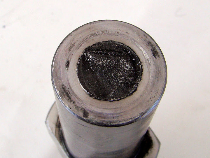
Screw end of failed pin |
Looking at the screw end of the pin the evidence of earlier cracking is more evident. The ‘polished’ areas of the failed pin evidence cracking that occurred at an earlier date that has since been ground smooth.
From this angle the diameter of the pin actually looks less than the minimum diameter of the screw thread. |
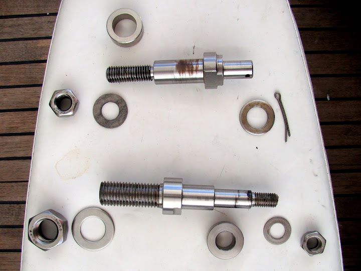
| Here are the old pin and the new pin along with all the additional pieces that go with them. Each pin screws into the flange and locked down with a washer and a nut (left of each pin).
The old pin then had a collar which went on the pin keeping the steering gear away from the flange. On the new pin this collar was integral to the pin and edges ground on to allow tightening. The old pin had an integral section further down which on the new pin was replaced with a removable collar. Finally, the old pin used a washer and a cotter pin to hold on the autopilot piston. On the new pin we have a washer and a locking nut. |
Old and new pin disassembled |
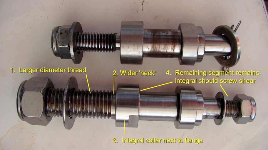 |
When loosely assembled the differences and similarities become more apparent. The specific improvements on the new pin are :-
|
|
Old and new pin partially assembled |
|
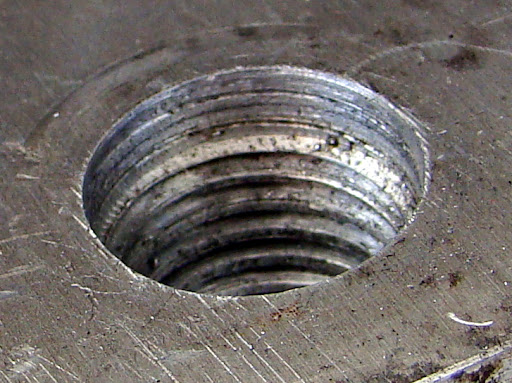
| The sockets in the flanges needed to be enlarged to match the larger screw threads on the pins.
To accommodate the wider ‘neck’ of the screw, the thread at one end of the socket had to be removed. |
Rebored flange thread |
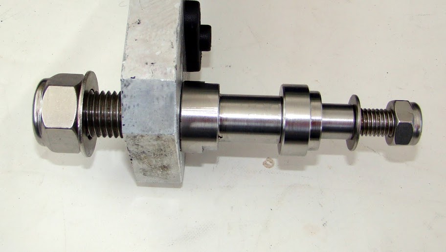 Partially assembled port flange and pin |
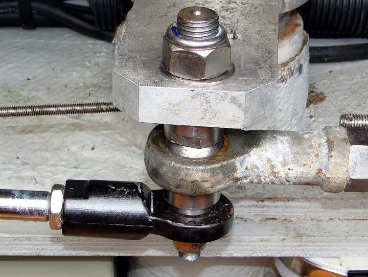
Here is one of the new pins screwed into the starboard flange. The top nut has yet to be tightened. |
| So here is the port pin fully assembled. Top to bottom are the nut, the flange (to the rudder post), the steering assembly going off to the right and the autopilot piston going off to the left. |
Port assembly |
 Starboard Assembly |
The starboard pin has no autopilot. An additional sleeve (bottom) was required to hold up the steering assembly. |

So how do these solutions compare? The chances of the new pin shearing in the same place are somewhat remote as it has a larger diameter screw, the screw terminates with a fatter ‘neck’ and the enlarged piece separating the flange from the steering assembly is integral to the pin, not a movable collar. If the new screw does break, the autopilot and steering assembly will remain linked making a jury rig significantly simpler than before.
Replacing the cotter pin with a nut at the bottom became necessary as this hold all the pieces on. I remain a little concerned about how well this nut will stay on but the way this was engineered, the nut locks on tight so it shouldn’t move. I will inspect from time to time.
The new pin may now be over-engineered with respect to failure prevention but that suits us. A simpler, but perhaps biggest bang for the buck, improvement would have been to keep the original design and simply implement enhancement 2 – the larger ‘neck’ accompanied by grinding out part of the thread in the flange. The extra 2-3mm diameter on the pin would probably increase its strength by 50%.
Because the largest metal diameter on the old and new pins are identical, the is no additional source material required bar the construction of the additional sleeve on the starboard pin. Our new design there brings significant improvement in strength for a minimal addition in cost of source materials and labour. Were the simpler improvement mentioned above implemented only a fractional increase in labour costs be required (for grinding out a few millimeters of thread in the flange) be required to gain a reasonable improvement in strength and more importantly, improved vessel safety.
Leave a Reply